Home » Without Label » 555 Timer Schematic / How Does Ne555 Timer Circuit Works Datasheet Pinout Eleccircuit Com - If you want to know all the pinout of the 555 timer, what each pin is and what each pin does, see 555 timer pinout.
555 Timer Schematic / How Does Ne555 Timer Circuit Works Datasheet Pinout Eleccircuit Com - If you want to know all the pinout of the 555 timer, what each pin is and what each pin does, see 555 timer pinout.
555 Timer Schematic / How Does Ne555 Timer Circuit Works Datasheet Pinout Eleccircuit Com - If you want to know all the pinout of the 555 timer, what each pin is and what each pin does, see 555 timer pinout.. A monostable 555 timer is required to produce a time delay within a circuit. The output voltage from the chip is around 1.5 v lower than vcc when high and around 0 v when low. A collection of 555 circuits using the 555 timer as an astable oscillator with different duty cycles. Timer, op amp, and optoelectronic circuits & projects. Adjustable on off timer(using 555 astable mode) in this circuit a timer with cyclic on off operations is designed.
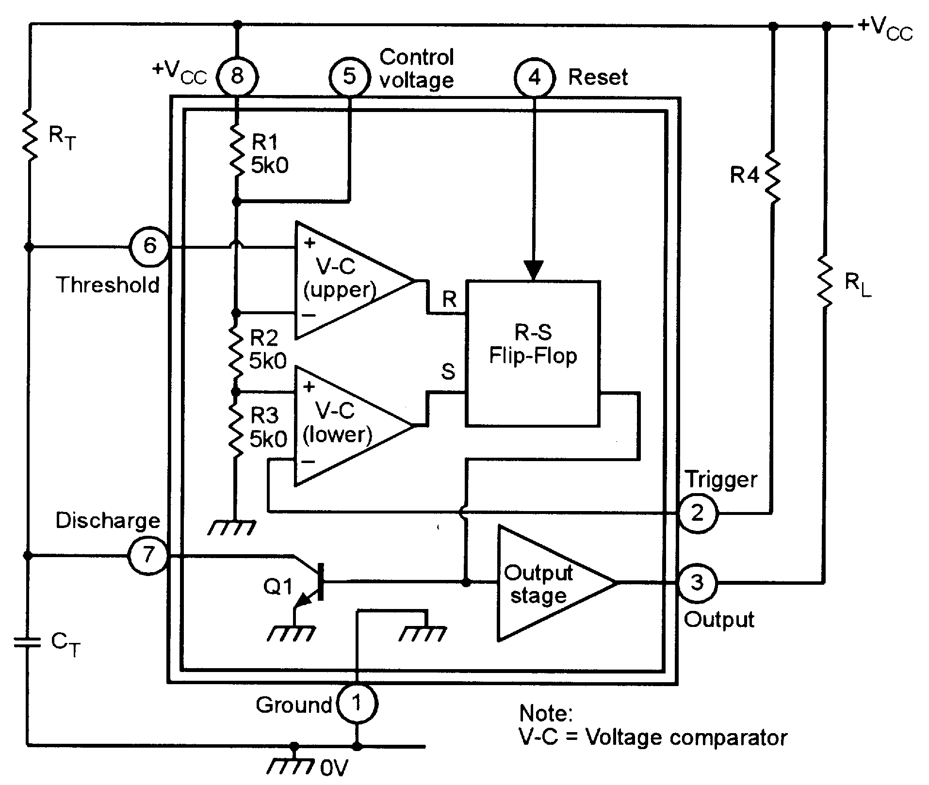
There are 24 different 555 timer circuits in this book! To understand the basic concept of the timer let' s first examine the timer in block form as in figure 1. Daman shah june 5, 2021. Adjustable on off timer(using 555 astable mode) in this circuit a timer with cyclic on off operations is designed. In this mode, the circuit of the ic 555 timer produces the continuous pulses with exact frequency primarily based on the value of the two resistors and.
555 Timer Ic Wikipedia from upload.wikimedia.org Basic 555 monostable multivibrator circuit. The 555 timer is a chip that can be us… Being an integral part of electronics project, 555 timer ic is very often used in simple to complex electronics projects. 500ms is the same as saying 0.5s so by rearranging the formula above, we get the calculated value for the resistor, r as: The values of r1 and c1 determine how long the output will remain high. The breadboard schematic of the above circuit is shown below. To understand the basic concept of the timer let' s first examine the timer in block form as in figure 1. In this project, we are using 555 timer ic to create various timer circuit like 1 min timer circuit, 5 min timer circuit, 10 min timer circuit, and 15 min timer circuit.
The 555 timer delay before turn on circuit we will build is shown below.
The working modes of a 555 timer are astable, bistable, and monostable. Referring to the timing diagram in figure 3, a low voltage pulse applied to the trigger input (pin 2) causes the output voltage at pin 3 to go from low to high. Also, 555 timer is used to generate an oscillating pulse. 555 timer was first introduced by signetics corporation in 1971 as se555/ne555. The timer's internal circuitry is largely responsible for this triggering but it is also caused stray or installed capacitance at the trigger input of the timer. In this category, we have handpicked some really useful 555 timer circuits which will be interesting to electronics engineering students and hobbyists alike. Ic 555 timer is a one of. Simple 555 timer circuits & projects. There are 24 different 555 timer circuits in this book! Each mode of operation indicates a circuit diagram and its output. In this project, we are using 555 timer ic to create various timer circuit like 1 min timer circuit, 5 min timer circuit, 10 min timer circuit, and 15 min timer circuit. We connect a 100μf capacitor to the positive voltage supply and then to pin 2. Its name is derived from three 5k ohm resistors ,connected in series used in it.the timer ic can produce required waveform accurately.
Additional • timing from microseconds through hours terminals are provided for triggering or resetting if • operates in both astable and monostable modes desired. In 2017, it was said over a billion 555 timers are produced. Monostable 555 timer circuits will automatically trigger and start a timing cycle when power is applied to the circuit. The circuits explained here are 10 best small timer circuits using the versatile chip ic 555, which generates predetermined time intervals in response to momentary input triggers. In this project, we are using 555 timer ic to create various timer circuit like 1 min timer circuit, 5 min timer circuit, 10 min timer circuit, and 15 min timer circuit.
555 Monostable Circuits Nuts Volts Magazine from www.nutsvolts.com The 555 ic timer circuit above shows a very straightforward design where the ic 555 forms the central controlling part of the circuit. Additional • timing from microseconds through hours terminals are provided for triggering or resetting if • operates in both astable and monostable modes desired. 555 timer circuits electronics circuit electronics basics electronics components. For a great resource on the 555 timer, opamps, and other ic's check out the engineer's mini notebook: The circuits explained here are 10 best small timer circuits using the versatile chip ic 555, which generates predetermined time intervals in response to momentary input triggers. 555 ic timer block diagram 555 ic timer block diagram. Daman shah june 5, 2021. The timer's internal circuitry is largely responsible for this triggering but it is also caused stray or installed capacitance at the trigger input of the timer.
A monostable 555 timer is required to produce a time delay within a circuit.
Here, with the help of the 555 timer ic, we are eliminating the need of manually switching on or off the device. The 555 timer can be obtained very cheaply from pretty much any electronic retailer. Working modes of 555 timer ic. We connect a 100μf capacitor to the positive voltage supply and then to pin 2. The 555 timer ic is an integrated circuit (chip) used in a variety of timer, delay, pulse generation, and oscillator applications. In this mode, the circuit of the ic 555 timer produces the continuous pulses with exact frequency primarily based on the value of the two resistors and. The values of r1 and c1 determine how long the output will remain high. This tutorial provides sample circuits to set up a 555 timer in monostable, astable, and bistable modes as well as an in depth discussion of how the 555 timer works and how to choose components to use with it. A collection of 555 circuits using the 555 timer as an astable oscillator with different duty cycles. 555 timer circuits electronics circuit electronics basics electronics components. The 555 ic timer circuit above shows a very straightforward design where the ic 555 forms the central controlling part of the circuit. The timer's internal circuitry is largely responsible for this triggering but it is also caused stray or installed capacitance at the trigger input of the timer. The circuits explained here are 10 best small timer circuits using the versatile chip ic 555, which generates predetermined time intervals in response to momentary input triggers.
The output voltage from the chip is around 1.5 v lower than vcc when high and around 0 v when low. The 555 timer is a chip that can be us… 555 timer was first introduced by signetics corporation in 1971 as se555/ne555. The 555 ic timer circuit above shows a very straightforward design where the ic 555 forms the central controlling part of the circuit. For a great resource on the 555 timer, opamps, and other ic's check out the engineer's mini notebook:
Https Encrypted Tbn0 Gstatic Com Images Q Tbn And9gcqxb7ja Fz7p3g1p3gvo Awb3y9tz4kcygfkcoafh Gdxfky0jr Usqp Cau from Referring to the timing diagram in figure 3, a low voltage pulse applied to the trigger input (pin 2) causes the output voltage at pin 3 to go from low to high. 555 timer is an industrial standard ic existing from early days of ic. As we know 555 timer ic is one of the commonly used ic among students and hobbyists. The values of r1 and c1 determine how long the output will remain high. 555 timer was first introduced by signetics corporation in 1971 as se555/ne555. Working modes of 555 timer ic. If you want to know all the pinout of the 555 timer, what each pin is and what each pin does, see 555 timer pinout. The working modes of a 555 timer are astable, bistable, and monostable.
A collection of 555 circuits using the 555 timer as an astable oscillator with different duty cycles.
We connect a 100μf capacitor to the positive voltage supply and then to pin 2. The effect is quite dramatic. The 555 timer delay before turn on circuit we will build is shown below. Working modes of 555 timer ic. 555 timer was first introduced by signetics corporation in 1971 as se555/ne555. Being an integral part of electronics project, 555 timer ic is very often used in simple to complex electronics projects. The 555 timer ic is an integrated circuit (chip) used in a variety of timer, delay, pulse generation, and oscillator applications. Additional • timing from microseconds through hours terminals are provided for triggering or resetting if • operates in both astable and monostable modes desired. As we know 555 timer ic is one of the commonly used ic among students and hobbyists. Daman shah june 5, 2021. 555 timer is an industrial standard ic existing from early days of ic. 555 timer circuits (133) browse through a total of 133 555 timer circuits and projects including the timer's datasheet. Adjustable on off timer(using 555 astable mode) in this circuit a timer with cyclic on off operations is designed.